

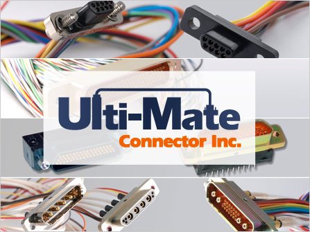

Ulti-Mate Connector, Inc. has been producing world-class Micro-miniature connectors and interconnect solutions since 1977. Their expertise in the design and production of customized solutions to the most demanding customer requirements has made Ulti-Mate a valued supplier to the OEM Marketplace.
Ulti-Mate specializes in serving the unique interconnect needs of military, space, aviation, medical, and geophysical exploration marketplaces. Innovation and quality has placed Ulti-Mate connectors in many of our country’s most advanced missile systems, manned space and satellite vehicles, and guidance and navigation systems. Ulti-Mate has a long history of meeting the rigorous specifications of invasive and noninvasive medical imaging, patient monitoring and measured drug delivery markets.
A family of microminiature center jackscrew connectors. The JSB Series, is available with layouts of 10, 11, 26 and 35 contacts. The JSB Series has a full range of terminations including cable to cable, board to cable, board to board.
| Contact Resistance | 8 mO Maximum @ 2.5 A |
|---|---|
| Current Rating | 3.0 A Maximum |
| Dielectric Withstanding Voltage | 900 VAC at sea level, 300 VAC @ 70,000 ft. Solder cups and shielded cable same as MIL-DTL-83513; 600 VAC at sea level 150VAC @ 70,000 ft. |
| Insulation Resistance | 5,000 MO Minimum |
6 oz. max per MIL-DTL-83513 (contact average is 3 oz.); Separation force is 5.0 oz. minimum.
Mate = 10 oz. X number of contacts maximum. Unmate = 10.5 oz. X number of contacts minimum.
| Vibration | No damage or interruption detected (one microsecond sensitivity) when subjected to Method 2005, Test Condition IV of MIL-STD-1344. |
|---|---|
| Shock | No damage or interruption detected (one microsecond sensitivity) when subjected to Test Condition E. Method 2004 of MIL-STD-1344. |
| Durability | No mechanical defects after 500 matings; Test criteria are mating force, contact resistance, contact engagement, and separation forces. |
| Salt Spray | No exposure of base metal due to corrosion; no loss of performance as in durability above. |
| Pin Contacts | Beryllium Copper (C17200) per ASTM B194. |
|---|---|
| Socket Contacts | Copper alloy (C21000) per ASTM B36 or leaded commercial bronze (C314000) per ASTM B140. |
| Contact Plating | Gold plated per MIL-DTL-45204D. 50 microinches min. is the standard thickness. |
| Metal Shells | Aluminum alloy per SAE-AMS-QQ-A-200/8, type 6061-T6. Finish is cadmium per SAE-AMS-QQ-P-416, TYPE II, CLASS 3, with suitable underplate with yellow chromate, this plating is not RoHS compliant. Or Finish Electroless Nickel plate per SAE AMS2404, class 3 or 4, .0005 minimum thickness. |
| Insulator Material | Preferred material is Polyphenylene sulfide (PPS) per MIL-M-24519 or ASTM D5927 GST 40F. Color Black. |
| LCP | Liquid Crystal Polymer-Vectra 130 (optional). |
| Interfacial Seals | Fluorosilicone elastomer per MIL-R-25988. Standard on M Series socket face. |
| Hardware | Stainless Steel, passivated. |
 |
|||||||||||||||
|
|||||||||||||||