


Ulti-Mate Connector, Inc. has been producing world-class Micro-miniature connectors and interconnect solutions since 1977. Their expertise in the design and production of customized solutions to the most demanding customer requirements has made Ulti-Mate a valued supplier to the OEM Marketplace.
Ulti-Mate specializes in serving the unique interconnect needs of military, space, aviation, medical, and geophysical exploration marketplaces. Innovation and quality has placed Ulti-Mate connectors in many of our country’s most advanced missile systems, manned space and satellite vehicles, and guidance and navigation systems. Ulti-Mate has a long history of meeting the rigorous specifications of invasive and noninvasive medical imaging, patient monitoring and measured drug delivery markets.
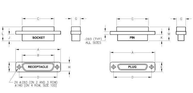
| All | A & P Low profile Series | |||||||||
| Size | A Max. | B Max. | C Max. | H Max | ||||||
| 9 | .785 (19.94) | .371 (9.42) | .399 (10.13) | .215 (5.46) | ||||||
| 15 | .935 (23.75) | .521 (13.23) | .549 (13.94) | .215 (5.46) | ||||||
| 21 | 1.085 (27.56) | .671 (17.04) | .699 (17.75) | .215 (5.46) | ||||||
| 25 | 1.185 (30.10) | .771 (19.58) | .799 (20.29) | .215 (5.46) | ||||||
| 31 | 1.335 (33.91) | .921 (23.39) | .949 (24.10) | .215 (5.46) | ||||||
| 37 | 1.485 (37.72) | 1.071 (27.20) | 1.099 (27.91) | .215 (5.46) | ||||||
| 51 | 1.435 (36.45) | 1.019 (25.88) | 1.046 (26.57) | .255 (6.48) | ||||||
| 100 | 2.165 (54.99) | N/A | N/A | N/A | ||||||
*3D Models are standard profile without hardware. Consult factory for other configurations and low profile (A & P) versions.
| M & B Standard Series | ||||||||||
| Size | B Max. | C Max. | H Max. | |||||||
| 9 | .402 (10.21) | .393 (9.98) | .248 (6.30) | |||||||
| 15 | .552 (14.02) | .543 (13.79) | .248 (6.30) | |||||||
| 21 | .702 (17.83) | .693 (17.60) | .248 (6.30) | |||||||
| 25 | .802 (20.37) | .793 (20.14) | .248 (6.30) | |||||||
| 31 | .952 (24.18) | .943 (23.95) | .248 (6.30) | |||||||
| 37 | 1.102 (27.99) | 1.093 (27.76) | .248 (6.30) | |||||||
| 51 | 1.054 (26.77) | 1.041 (26.44) | .297 (7.54) | |||||||
| 100 | 1.503 (38.18) | 1.433 (36.40) | .391 (9.93) | |||||||
Sales Drawings
Male Micro-D Size(9-37) PDF file
Male Micro-D Size(51) PDF file
Male Micro-D Size(100) PDF file
Female Micro-D Size(9-37) PDF file
Female Micro-D Size(51) PDF file
Female Micro-D Size(100) PDF file
| 3D Models* | ||||||||||
| Size | Male | Female | ||||||||
| 9 | 834111070.STP | 834211070.STP | ||||||||
| 15 | 834121070.STP | 834221070.STP | ||||||||
| 21 | 834131070.STP | 834231070.STP | ||||||||
| 25 | 834141070.STP | 834241070.STP | ||||||||
| 31 | 834151070.STP | 834251070.STP | ||||||||
| 37 | 834161070.STP | 834261070.STP | ||||||||
| 51 | 834171070.STP | 834271070.STP | ||||||||
| 100 | 834181070.STP | 834281070.STP | ||||||||
| Rows | Series | E Max | G Max | J Max Skt | ||||||
| 2 | A & P | .218 (5.54) | .174 (4.42) | .182 (4.62) | ||||||
| 2 | M & B | .300 (7.62) | .275 (6.99) | .199 (5.05) | ||||||
| 3 | A & P | .254 (6.45) | .223 (5.66) | .182 (4.62) | ||||||
| 3 | M & B | .342 (8.69) | .312 (7.92) | .199 (5.05) | ||||||
| 4 | M & B | .392 (9.96) | .352 (8.94) | .199 (5.05) | ||||||
| Rows | K Max Pin | L Max Skt | M Max Pin | |||||||
| 2 | .202 (5.13) | .369 (9.37) | .385 (9.78) | |||||||
| 2 | .187 (4.75) | .429 (10.90) | .415 (10.54) | |||||||
| 3 | .202 (5.13) | .369 (9.37) | .385 (9.78) | |||||||
| 3 | .187 (4.75) | .429 (10.90) | .415 (10.54) | |||||||
| 4 | .187 (4.75) | .429 (10.90) | .415 (10.54) | |||||||
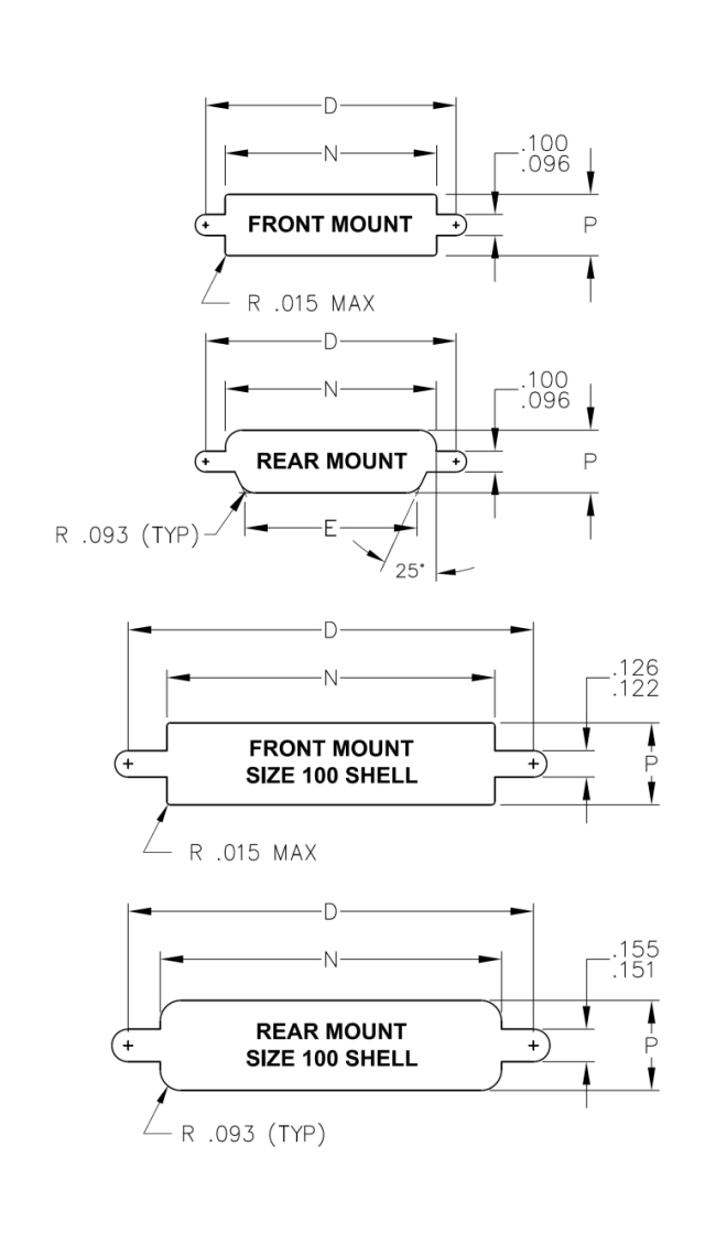
| A & P Low profile Series | ||||||||||
| Front Mount | Rear Mount | |||||||||
| Size | D | N+.006/-.00 | P | N+.006/-.00 | P | |||||
| 9 | .565 (14.35) | .405 (10.29) | .180 (4.57) | .377 (9.58) | .221 (5.61) | |||||
| 15 | .715 (18.16) | .555 (14.10) | .180 (4.57) | .527 (13.39) | .221 (5.61) | |||||
| 21 | .865 (21.97) | .705 (17.91) | .180 (4.57) | .677 (17.20) | .221 (5.61) | |||||
| 25 | .965 (24.51) | .805 (20.45) | .180 (4.57) | .777 (19.74) | .221 (5.61) | |||||
| 31 | 1.115 (28.32) | .955 (24.26) | .180 (4.57) | .927 (23.55) | .221 (5.61) | |||||
| 37 | 1.265 (32.13) | 1.105 (28.07) | .180 (4.57) | 1.077 (27.36) | .221 (5.61) | |||||
| 51 | 1.215 (30.86) | 1.052 (26.72) | .229 (5.82) | 1.025 (26.04) | .261 (6.63) | |||||
| 100 | N/A | N/A | N/A | N/A | N/A | |||||
| M & B Standard Series | ||||||||||
| Front Mount | Rear Mount | |||||||||
| Size | D Max | N+.006/-.00 | P | N+.006/-.00 | P | |||||
| 9 | .565 (14.35) | .405 (10.29) | .281 (7.14) | .408 (10.36) | .254 (6.45) | |||||
| 15 | .715 (18.16) | .555 (14.10) | .281 (7.14) | .558 (14.17) | .254 (6.45) | |||||
| 21 | .865 (21.97) | .705 (17.91) | .281 (7.14) | .708 (17.98) | .254 (6.45) | |||||
| 25 | .965 (24.51) | .805 (20.45) | .281 (7.14) | .808 (20.52) | .254 (6.45) | |||||
| 31 | 1.115 (28.32) | .955 (24.26) | .281 (7.14) | .958 (24.33) | .254 (6.45) | |||||
| 37 | 1.265 (32.13) | 1.105 (28.07) | .281 (7.14) | 1.108 (28.14) | .254 (6.45) | |||||
| 51 | 1.215 (30.86) | 1.052 (26.72) | .318 (8.08) | 1.060 (26.92) | .303 (7.70) | |||||
| 100 | 1.800 (45.72) | 1.439 (36.55) | .358 (9.09) | 1.509 (38.33) | .397 (10.08) | |||||
| Contact Resistance | 8 mO Maximum @ 2.5 A |
|---|---|
| Current Rating | 3.0 A Maximum |
| Dielectric Withstanding Voltage | 900 VAC at sea level, 300 VAC @ 70,000 ft. Solder cups and shielded cable same as MIL-DTL-83513; 600 VAC at sea level 150VAC @ 70,000 ft. |
| Insulation Resistance | 5,000 MO Minimum |
6 oz. max per MIL-DTL-83513 (contact average is 3 oz.); Separation force is 5.0 oz. minimum.
Mate = 10 oz. X number of contacts maximum. Unmate = 10.5 oz. X number of contacts minimum.
| Vibration | No damage or interruption detected (one microsecond sensitivity) when subjected to Method 2005, Test Condition IV of MIL-STD-1344. |
|---|---|
| Shock | No damage or interruption detected (one microsecond sensitivity) when subjected to Test Condition E. Method 2004 of MIL-STD-1344. |
| Durability | No mechanical defects after 500 matings; Test criteria are mating force, contact resistance, contact engagement, and separation forces. |
| Salt Spray | No exposure of base metal due to corrosion; no loss of performance as in durability above. |
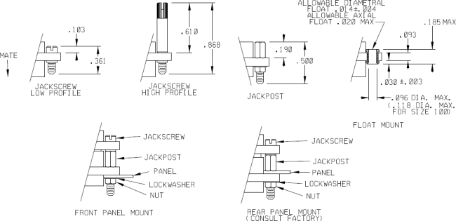
| Description | Mil Spec | UMI | A Max. | B Max. |
| Jackscrew Lo Allen | M83513/05-02 | 83041xxxx | .361 (9.17) | .103 (2.62) |
| Jackscrew Hi Allen | M83513/05-03 | 83041xxxx | .868 (22.05) | .610 (15.49) |
| Jackscrew Lo Slot | M83513/05-05 | 83041xxxx | .361 (9.17) | .103 (2.62) |
| Jackscrew Hi Slot | M83513/05-06 | 83041xxxx | .868 (22.05) | .610 (15.49) |
| Jackpost | M83513/05-07 | 83041xxxx | .500 (12.70) | .190 (4.83) |
| Jackscrew Lo Allen | M83513/05-12 | 83041xxxx | .390 (9.91) | .103 (2.62) |
| Jackscrew Hi Allen | M83513/05-13 | 83041xxxx | .902 (22.91) | .610 (15.49) |
| Jackscrew Lo Slot | M83513/05-15 | 83041xxxx | .390 (9.91) | .103 (2.62) |
| Jackscrew Hi Slot | M83513/05-16 | 83041xxxx | .902 (22.91) | .610 (15.49) |
| Jackpost | M83513/05-17 | 83041xxxx | .500 (12.70) | .185 (4.70) |
| Description | Thread | Used on Sizes | 3D Models |
| Jackscrew Lo Allen | 2-56 UNC-2A | M83513/05-02.STP | |
| Jackscrew Hi Allen | 2-56 UNC-2A | 9 | M83513/05-03.STP |
| Jackscrew Lo Slot | 2-56 UNC-2A | through | M83513/05-05.STP |
| Jackscrew Hi Slot | 2-56 UNC-2A | 51 | M83513/05-06.STP |
| Jackpost | 2-56 UNC-2B | M83513/05-07.STP | |
| Jackscrew Lo Allen | 4-40 UNC-2A | M83513/05-12.STP | |
| Jackscrew Hi Allen | 4-40 UNC-2A | M83513/05-13.STP | |
| Jackscrew Lo Slot | 4-40 UNC-2A | 100 | M83513/05-15.STP |
| Jackscrew Hi Slot | 4-40 UNC-2A | M83513/05-16.STP | |
| Jackpost | 4-40 UNC-2B | M83513/05-17.STP | |
| Pin Contacts | Beryllium Copper (C17200) per ASTM B194. |
|---|---|
| Socket Contacts | Copper alloy (C21000) per ASTM B36 or leaded commercial bronze (C314000) per ASTM B140. |
| Contact Plating | Gold plated per MIL-DTL-45204D. 50 microinches min. is the standard thickness. |
| Metal Shells | Aluminum alloy per SAE-AMS-QQ-A-200/8, type 6061-T6. Finish is cadmium per SAE-AMS-QQ-P-416, TYPE II, CLASS 3, with suitable underplate with yellow chromate, this plating is not RoHS compliant. Or Finish Electroless Nickel plate per SAE AMS2404, class 3 or 4, .0005 minimum thickness. |
| Insulator Material | Preferred material is Polyphenylene sulfide (PPS) per MIL-M-24519 or ASTM D5927 GST 40F. Color Black. |
| LCP | Liquid Crystal Polymer-Vectra 130 (optional). |
| Interfacial Seals | Fluorosilicone elastomer per MIL-R-25988. Standard on M Series socket face. |
| Hardware | Stainless Steel, passivated. |
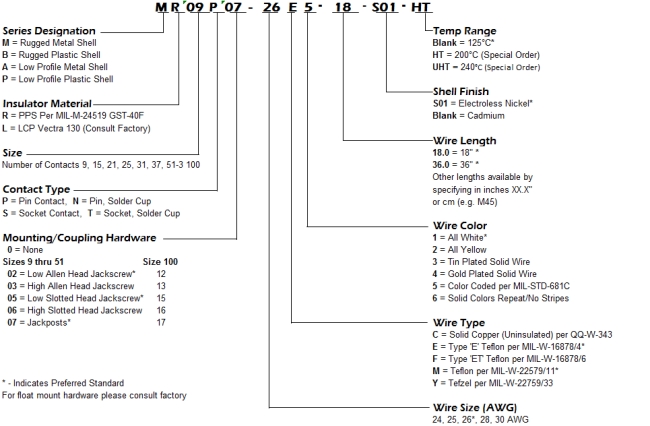
A, P, M, and B Series 50 mil Rectangular Connectors, P and M series are in accordance with MIL-DTL-83513
Click image to view larger image view
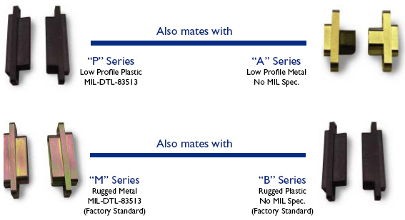
Select the type of rectangular connector you require. Note the “P” series of MIL-DTL-83513 is not designed to mate with the MIL-DTL-83513 “M” series. The “M” series mates with its dimensional plastic version “B”. The “A” series mates with its dimensional plastic version “P”.
 |
|||||||||||||||
|
|||||||||||||||