


Ulti-Mate Connector, Inc. has been producing world-class Micro-miniature connectors and interconnect solutions since 1977. Their expertise in the design and production of customized solutions to the most demanding customer requirements has made Ulti-Mate a valued supplier to the OEM Marketplace.
Ulti-Mate specializes in serving the unique interconnect needs of military, space, aviation, medical, and geophysical exploration marketplaces. Innovation and quality has placed Ulti-Mate connectors in many of our country’s most advanced missile systems, manned space and satellite vehicles, and guidance and navigation systems. Ulti-Mate has a long history of meeting the rigorous specifications of invasive and noninvasive medical imaging, patient monitoring and measured drug delivery markets.
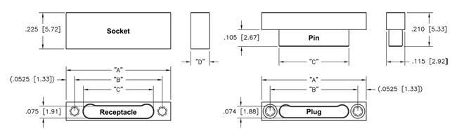
| Size | "A" | "B" | Plug "C" Receptacle | Metal "D" Plastic | ||
| 9 | .500 [12.70] | .395 [10.03] | .284 [7.21] | .285 [7.24] | .115 [2.92] | .120 [3.05] |
| 15 | .650 [16.51] | .545 [13.84] | .434 [11.02] | .435 [11.05] | .115 [2.92] | .120 [3.05] |
| 21 | .800 [20.32] | .695 [17.65] | .584 [14.83] | .585 [14.86] | .115 [2.92] | .120 [3.05] |
| 25 | .900 [22.86] | .795 [20.19] | .684 [17.37] | .685 [17.40 | .115 [2.92] | .120 [3.05] |
| 31 | 1.050 [26.67] | .945 [24.00] | .834 [21.18] | .835 [21.21] | .115 [2.92] | .120 [3.05] |
| 37 | 1.200 [30.48] | 1.095 [27.81] | .984 [24.99] | .985 [25.02] | .115 [2.92] | .120 [3.05] |
| 51 | 1.550 [39.37] | 1.445 [36.70] | 1.334 [33.88] | 1.335 [33.91] | .115 [2.92] | .120 [3.05] |
|
Sales Drawings |
||||||
|
For .stp files, please refer to the following link: |
||||||
| Contact Resistance | 0.071 volt maximum drop @ 1.0 amps (.071 ohms) |
|---|---|
| Current Rating | 1.0 Amp Maximum per contact |
| Dielectric Withstanding Voltage | 250 V, RMS, 60Hz |
| Insulation Resistance | 5,000 Megohms Minimum @ 100 VDC |
5 Ounce Maximum, 0.4 Ounce Minimum
#30–#32 AWG
| Vibration | Tested in accordance with EIA–364–28, Condition IV. No Damage or resistance change greater than 10 omhs lasting longer than 10 ns |
|---|---|
| Shock | Tested in accordance with EIA–364–27, Condition G. No Damage or resistence change greater than 10 ns |
| Durability | 200 connector mating cycles tested in accordance with EIA–364–09. No Damage or resistance change greater than 10ohms lasting longer than 10ns |
| Salt Spray | Mated connectors tested in accordance with EIA–364–26, Condition B. No exposure to base metal |
| Humidity | Mated connectors tested in accordance with EIA–364–31, Condition B (except steps 7a and 7b). Meet DWV and IR Requirements |
| Pin & Socket Contacts | Pins: BeCu alloy strip per ASTM–B–194 / Sockets: BeCu per ASTM–B–194 |
|---|---|
| Contacts Plating | Gold plate per ASTM B488, or SAE AMS 2422 |
| Metal Shells | Aluminum with electroless nickel or electrodeposited cadmium plating, Stainless Steel per ASTM A582, Titanium Alloy per MIL–T–81556, Unplated |
| Molded Insulators into Metal housing or Full plastic housing: | Insulating compound per MIL–I–16923. Liquid Crystal Polymer (LCP), per MIL–M–24519 GLCP–30F, 30% Glass |
| Hardware | Corrosion resistant steel per ASTM A 582/A582 or ASTM A 581/A581M, Passivated per SAE AMS–2700 |
 |
|||||||||||||||
|
|||||||||||||||